Locking threaded fasteners is essential to prevent bolted joints from becoming loose.
Engineers designing new bolted joints, fasteners manufacturers and distributors rely on the fastener transverse vibration test to compare the relative performance of fastener locking solutions and design safer products.
The Junker test procedures described in ISO 16130, DIN 65151 and DIN 25201-4 B standards allow the collection of accurate and repeatable test data. An unsecured fastener sample is submitted to transverse vibration cycles, at increasing displacement values, until it self-loosens. The secured joint is then tested in the same conditions.
The preload is plotted against the number of load cycles to assess the secured fastener self-loosening behaviour.
With additional data such as the transverse force, the tightening torque and friction coefficient, the detailed dynamic analysis of the fastener performance aids engineers specify the safest fastening solution for a given application.
Step 1 – the Reference test
To start the reference test, the unsecured bolted joint – the fastener without fastener locking element – must be placed in the test bench. Starting from zero, the displacement is gradually increased until the fastener self-loosens after 300 load cycles, ±100 load cycles. Once this efficient displacement is achieved, three subsequent refer- ence tests with fresh components are required to ensure that the initial reference test results are consistent.
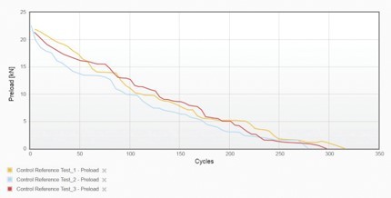
Figure 1 shows three control reference tests conducted on an unsecured bolted joint without locking element
Step 2 – the Verification test
The next stage is to conduct the verification test. The exact same test conditions are set including the same effective displacement. Then, the locking product is introduced and the secured bolted joint
is tested to find out if and at what point the secured bolted joint starts to loosen. There must be a number of verification tests to ensure test reproducibility.
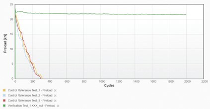
Figure 2 shows the verification test of the fastener mounted with the locking product, under the same test parameters as the control references on Figure 1
Reporting and documenting
The remaining preload in the bolted joint must be plotted against the number of load cycles in a graph. The securing effect is then assessed according to the percentage of preload remaining after 2000 load cycles.
Based on the plot of the preload against the number of load cycles, the preload curve must show that it is unlikely that the fastener would have failed if the test continued beyond 2000 cycles.
In the test report, the type of locking mechanism and its fitting position must be described, together with the test frequency, clamp length to diameter ratio, clamping, effective transverse displacement and lubrication used.
The final part of the report should detail the conditions under which the fastener’s securing element can be used, and if the test determined it, the level of pre-stressing force at which the fastener can be expected to fail. Details such as lubrication, surface coatings and the range of diameters are also required.
Learn how to conduct a fastener vibration test according to DIN 65151, DIN 25201-4 or ISO 16130.