
Last updated on October 3, 2023 by Morten Schiff
Abstract. Vibration can be desirable, such as when it is used to make music. More often, however, vibration is undesirable. It can introduce stress into mechanical systems and create fatigue that decreases service life. It can also loosen fasteners.
This article discusses the root causes of the self-loosening of fasteners, then two practical examples illustrate the benefits and possible applications of vibration testing of fasteners, according to either standardised testing protocols or customised testing strategies simulating real-life conditions of the assembled parts. The requirements and protocols of the international standard ISO 16130, the USA national aerospace standard NASM 1312-7, the German national standard DIN 25201-4 B and its predecessor DIN 65151 are compared, with insights on their most suitable applications. Finally, the article describes a lean methodology to design a meaningful testing protocol.
1 Introduction
Vibration can be desirable. For example, it can be controlled to make music or speech. More often, however, vibration is undesirable, wasting energy and creating unwanted noise and wear. It can introduce stress into mechanical systems and create fatigue that decreases service life. It can also loosen fasteners. When they loosen and fail, devices fail catastrophically. Production lines grind to a halt. Vehicles crash. Planes drop from the sky.
The vibration testing of fasteners is key to deliver safe engineering by ensuring that all fasteners are fit for purpose and will not fail in service. The applications of such testing range from validating engineering drawings and computer simulations, to certifying fasteners for OEM supply, to teaching or demonstrating competitive advantages of innovative fastening solutions.
2 The theory behind fastener self-loosening from transverse movement
Bolted joints can be easily disassembled. This is a major benefit, but it also presents the danger of unintentional loosening in operational conditions. To prevent self-loosening, it is important to understand how and why it occurs, as well as to have a means of testing to ensure safe and practical solutions.
Bolted joints rely on the clamping force, also called preload, that results from the tightening torque. The fastening will not come loose if the clamping force acting on the bolts is sufficient to overcome the transverse force and creates sufficient friction grip to prevent transverse movement between the clamped parts. However, if a transverse force acting on the joint is greater than the frictional resistance of the preload, relative motion occurs between the mating threads and the fastener bearing surface. In this case, the bolted joint will behave as a simple inclined plane. Repeated transverse movements can completely loosen fasteners.
2.1 Where does the tightening torque go?
To better understand the phenomenon of self-loosening, we first have to study the tightening process.
A tightening torque M_{A} is necessary to fasten a bolt. It is the combination of the torque related to the friction under the head M_{K}, the torque related to the friction in the threads M_{G}, and the torque related to the thread pitch (M_{TP}) [1]:
(1) M_{A} = M_{K} + M_{G} + M_{TP}
In many cases, the thread pitch torque M_{TP} , directly related to the bolt preload, represents only approximately 10% of the total tightening torque M_{A} (Fig. 1). An increase of only 5% of the friction under the head M_{K} or the friction in the threads M_{G} can lead to a reduction in preload of up to 50% [2].

Figure 1. Three torque components at work on a bolt
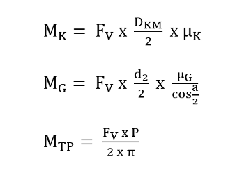
The torques related to the friction under the head M_{K}, the friction in the threads M_{G} and the thread pitch torque are calculated using the following formulas [1]:
(2) M_{K} = F_{V}x\frac{D_{KM}}{2}x\mu_{K}
(3) M_{G} = F_{V}x\frac{d_{2}}{2}x\frac{\mu_{G}}{cos\frac{a}{2}}
(4) M_{TP} = \frac{F_{V}xP}{2x\pi}
Where F_{V} = the preload in the bolt; \mu_{K} = friction under the head of the bolt; \mu_{G} = friction in the thread; P = thread pitch; D_{KM} = effective diameter for the friction in the bolt head or nut-bearing area; and d_{2} = thread pitch diameter.
In a bolted joint, the thread pitch torque M_{TP} is less than the combined friction in the thread M_{G} and under the head M_{K}. This is called self-locking. The tensile force generated by the elongation of the bolt shaft and by the force of compression generated in the objects being tightened remains balanced:
(5) M_{TP} < M_{k} + M_{G}
2.2 Why do bolted joints self-loosen?
In practice, most bolted joints experience influence from the surrounding environment. This can lead to a change in the balance (Equation 3) and a spontaneous decrease in the preload.
To loosen a bolted joint, the moment M_{L} is necessary:
(6) M_{L} = M_{K} + M_{G} - M_{TP}
The pitch torque M_{TP} works to unfasten the bolt. This is because of the helix angle of the thread pitch, also known as the internal off torque. Thus, when the internal off torque is larger than the retention moments M_{k} + M_{G}, rotational self-loosening will take place [3]:
(7) M_{TP} > M_{K} + M_{G}
2.3. Rotational self-loosening
The transverse movement required to overcome the frictional resisting force, also called ‘theoretical limiting displacement’ SG_{th} or ‘marginal slip’, can be calculated as follows [1]:
(8) SG_{th} = \frac{ F_{V} x \mu_{K} x L\frac{3}{K} }{ 12 x E x + 1 }
Where SG_{th} = theoretical limiting displacement; F_{V}= the preload in the bolt; \mu_{K} = friction under the head of the bolt; L_{K} = clamping length of the bolt; E = Young’s modulus of the bolt; and I = second moment of area of the bolt.
3 Practical applications of dynamic vibration testing of fasteners
Testing fasteners or complete bolted joints in service condition is the most practical way to compare the resistance to self-loosening of different fastening solutions, or to validate the fastener specifications selected for a mechanical design, respectively.
The Junker vibration test — named after Gerhard Junker, who published the breakthrough article “New Criteria for Self-Loosening of Fasteners Under Vibration” in 1969 [4] — has become the standard for dynamic testing of fasteners and analysis of their self-loosening behaviour.
3.1 Recommendations concerning the test rig and which data to collect
A dynamic vibration test bench applies a transverse oscillary motion on a glider plate to create cyclic vibration of variable frequency and amplitude. The bolted joint being tested clamps together the glider plate and a fixed plate. The clamping force is measured in real time and plotted on a graph.
A modern Junker test bench (Fig. 2) should comply with the requirements of ISO 16130 [5], DIN 25201-4 B [1] and the former DIN 65151 standards. The test rig should allow for the measurement of the transverse displacement and the transverse force applied to the fastener. It should also allow for the calculation of the fastener’s friction coefficient from the relationship between the applied torque and the achieved tension.
The test data should be displayed in a graphic chart (Fig. 2) with various visualisation filtering options and should be exportable in .CSV files for further analysis. Such Junker test benches allow for a highly accurate assessment of the fasteners’ self-locking performance, as well as statutory ISO and DIN testing.
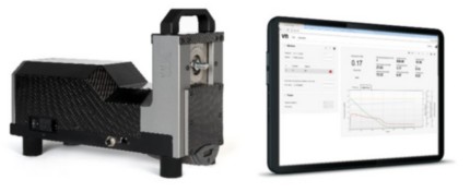
Figure 2. Vibrationmaster J121 fastener vibration and torque test bench, compliant with ISO 16130, DIN 25201-4 B and DIN 65151, with web-based user interface
3.2 Application example 1: how to compare different fastening solutions?
The development of new fastening products requires an understanding of their self-loosening behaviour. Fastener manufacturers and distributors rely on vibration testing to benchmark the performance of substitute products. Comparing the anti-loosening characteristics of locking solutions is also the object of many research articles [6-9] comparing the effect of parameters such as the clamping length, the surface finish and treatment, or various locking systems (e.g. wedge lock washers or chemical locking).
The fasteners being compared are submitted to a standardised vibration test, such as ISO 16130 or DIN 25201-4 B. The results are displayed in a chart plotting the measured clamping force against the number of load cycles (Fig. 3), to compare the resistance to self-loosening of the test samples.
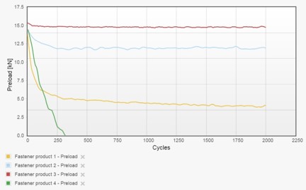
Figure 3. Comparison of the self-loosening behaviour of fasteners tested on Vibrationmaster J121
3.3 Application example 2: how to validate a new mechanical bolted joint design with a “tested-by-me” approach?
In the early design stage, engineers can validate their new bolted joint design with a bespoke vibration test reproducing the actual service condition of the application, also called “tested-by-me” protocol.
We have seen in section 2 that fasteners will not come loose if the clamping force acting on the joint is sufficient to overcome the external transverse force that the application meets during actual operation and to prevent movement between the clamped parts.
The “tested-by-me” approach involves building the bolted joint in the vibration test rig using the same material, dimensions and surface properties as in the actual application. In a vibration test, the bolted joint will be subjected to increasing vibration displacement and thereby transverse force, until the exact point at which the displacement and transverse force become large enough to overcome the frictional resistance in the joint, induce movement between the clamped parts and start rotational self- loosening. This point is known as the marginal slip. The design engineer will then compare the measured transverse force value from the vibration test rig to the requirement for the actual application.
A corrective coefficient factor C_{F} shall be applied to relate the measured transverse force in the test rig and the transverse force that would result from the same conditions in the application.
The maximal transverse force value that can be withstood by the bolted joint F_{R} in real conditions is:
(10) F_{R} = F_{T} x C_{F}
FRF_{R} can be compared to the calculated maximum transverse force F_{C} estimated for the application during the design stage. The bolted joint design is validated if the real transverse force required to self- loosen the bolted joint F_{R} is higher than the calculated transverse force handled by the application, as follows:
(11) F_{R} > F_{C}
4 Which tests are needed to stay safe?
The purpose of the test is to determine which standards and test regime are most appropriate for a particular application. If the purpose is to benchmark fasteners or to meet an insurance claim, ISO 16130 and DIN 25201-4 B provide standardised assessment of the self-loosening behaviour. In cases where it is more important that the tests reflect the real conditions of the application, it is recommended to apply more demanding bespoke test criteria, also called “tested-by-me” protocol.
4.1 A brief description of the three standards
Table 1. Brief description of DIN 25201-4 B, ISO 16130, NASM 1312-7 and “tested-by-me” protocols
| DIN 25201-4 B The toughest conditions | ISO 16130:2015 The standard for aerospace | NASM1312-7 For impact testing | Bespoke “tested-by-me” protocols |
|
The DIN 25201-4 B, published in 2010, supersedes DIN 65151 and is significantly more rigorous. It introduces manda- tory reference and verification tests, specifies quality tole- rances on the fastener adaptors in the test fixture, requires the use of a test washer, sets a standardised clamp ratio, defines the initial preload level and sets out strict test reporting procedures. The DIN 25201-4 B also sets criteria for eva- luating whether a locking element has adequate self-locking behaviour. |
The ISO 16130 is not as rigorous as DIN 25201-4 B but follows similar principles. It defines new tolerances on the test machine. It introduces torque measurements into a vibration test standard. Finally, ISO 16130 sets evaluation thresholds and specifies three quality levels for evaluating the self- locking behaviour of bolted joints. |
The “Fastener Test Methods 7 Vibration” was published by the Aerospace Industries Association of America in 1997 and is quite differrent from the Junker test. This test is an impact and shock test that involves securing the fasteners to be tested in cylinders mounted in slots within a reciprocating fixture. The fixture is vibrated at 30 Hz at an amplitude, peak to peak, of 0.45 inches (11.4mm). A problem with using this test to assess the self-loosening of fasteners is that the bolt preload is not measured during testing. |
These protocols represent an important experimental approach to testing for the real world. Testing products to meet specific performance characteristics beyond the conditions specified in the formal standards requires innovative testing strategies designed to replicate the real service conditions. This is a common-place occurrence in the automotive and defence-aerospace sectors, and the practice is spreading into other sectors. ‘Tested-by-me’ product development strategies result in improved products over the long term and a competitive edge that can be sustained. |
4.2 DIN or ISO? The testing standards and the choices you need to make
Table 2 compares the testing procedures and requirements of the ISO 16130 and DIN 25201-4 B standards.
| Testing criteria | ISO 16130 The standard for aerospace |
DIN 25201-4, B The toughest conditions | Authors’ comments |
| Hardware requirements | |||
| Test washer | Yes, secured from rotation | Yes, secured from rotation. Dimensions and roughness must comply with DIN EN ISO 7093-1 – Plane-parallelism and flatness must comply with DIN EN ISO 4759-3 – Hardness must be 200HV for fastener class up to 8.8 and 300HV for fastener class above 8.8 – Washers must be grounded |
A specified test washer must be used with each test in order to standardise embedding and ensure reproducible results |
| Fastener adaptors | Yes, secured from rotation | Yes, secured from rotation | |
| Test Bench requirements | |||
| Transverse displacement | Relative movement up to ±1.5mm for fasteners with dimensions up to 25.4mm / 1” UTS | Relative movement up to ±1.0mm shall be possible for fasteners with dimensions up to 24mm | |
| Fastener adaptors | Infinitely variable, preferably during operation and adjusted through electronic control | Infinitely variable | |
| Test frequency | 12.5Hz with a possible frequency range of 10Hz to 15Hz at an accuracy of ±3% | 12.5Hz | |
| Clamping force measurement uncertainty | ±2% as measured on the entire measuring chain | ±0.6% as measured on the entire measuring chain | |
| Transverse displacement measurement uncertainty | ±3% as measured on the entire measuring chain | ±3% as measured on the entire measuring chain | |
| Other tolerances | Clearance between stationary plate and glider plate must be 1mm ±0.05mm under load | Clearance between stationary plate and glider plate must be 1mm | |
| Stationary plate and glider plate shall be concentric within ±0.1mm | Stationary plate and glider plate shall be concentric | ||
| Test settings and requirements | |||
| Measured variables | Maximum self-locking torque | Only ISO includes a range of torque measurement in the test (we believe this makes ISO the most useful protocol) | |
| Necessary tightening torque value to achieve initial clamping force | |||
| Initial clamping force | Initial clamping force | ||
| Clamping force during test relative to cycles | Clamping force during test relative to cycles | ||
| Transverse displacement under load | |||
| Maximum self-locking torque after vibration test | |||
| Testing temperature | |||
| Reference test to assess the effective displacement | Assess the effective displacement that makes an unsecured joint self-loosen within 300 cycles ±100 cycles | Assess the effective displacement that makes an unsecured joint self-loosen within 300 cycles ±100 cycles | |
| Verification test | Verification tests (3x) must be completed | Verification tests (12x) must be completed with a duration of 2,000 cycles or until complete loss of clamping force | 3 tests should be sufficient with good test equipment delivering reproducible results |
| Reuse of fasteners | Allowed if parts are not visually damaged. | Not allowed | Pre-stressed elements should NEVER be allowed to be re- used. A used fastener will be elongated and may have exceeded its yield strength and changed material properties |
| Initial clamping force | 75% of calculated ultimate clamping force | 50% of VDI 2230 with μtot total coefficient of friction = 0.14 | |
| Clamp ratio (fastener length to diameter ratio) | As short as possible, preferably around 1:2.0 to 1:2.5 | 1:1.7 | The clamp ratio is very important when testing. The lower the ratio, the greater risk of self-loosening. This is particularly important in view of current trends to use short fasteners |
| Use of lubrication | Yes. SAE30 for steel parts and molybdenum sulphide paste for stainless or electro- galvanized parts | Lubricating the fasteners is important to obtain reproducible friction values and test results | |
| Test evaluation and reporting | |||
| Evaluation method | – Number of cycles until complete loss, or – Residual clamping force following a defined number of cycles, or – Number of cycles until fatigue fracture of the bolt |
Residual clamping force after 2,000 cycles | |
| Evaluation of self-locking behaviour | – 100% to 85% residual preload = Good self-locking behaviour – 85% to 40% residual preload = Acceptable loss of preload – 40% to 0% residual preload = Poor self-locking behaviour |
100% to 80% residual clamping force after 2,000 cycles = Aadequate self- locking behaviour | The residual preload is crucial – 60% loosening cannot be acceptable (the DIN approach is more rigorous) |
| Test report requirements | All test parameters, information about the tested fastener system, test bench manufacturer and model, fasteners used, name of testing laboratory, date of testing, inspector name, lot number of the tested fasteners | The type of test fittings used, the test parameters, test bench manufacturer and model, the result of the test including graph of clamping force against cycles, the permissible usage of the securing element | |
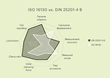
4.3 A summary chart to compare ISO 16130 and DIN 25201-4 B standards
Table 2 above is very detailed; however, a simpler data visualisation method can be designed to illustrate the difference between ISO 16130 and DIN 25201-4 B standards. The various parameters are grouped into 10 categories. An arbitrary rating from 0 to 10 is attributed to each category, where grade 10 is the toughest, most accurate, and most repeatable criterion, to obtain a radar comparison graph (Fig. 4):
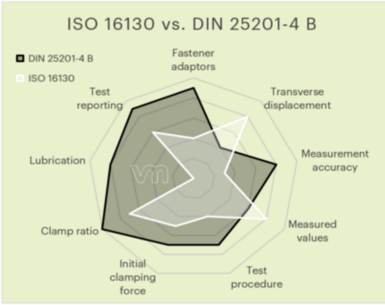
Figure 4. Comparison chart between ISO 16130 and DIN 25201-4 B
Even though ISO 16130 requires additional measurements (e.g., the maximum self-locking torque) and allows for larger displacement values, DIN 25201-4 B is more consistent and adds criteria like lubrication, tighter tolerances on washers and increased accuracy on measured values. Also, the DIN 25201-4 B requires a new test washer and sample for each test, which prevents embedding and improves the reproducibility of the test results.
5 Testing with rigour: how to conduct DIN 25201-4 B or ISO 16130 tests?
Dynamic testing of the self-loosening behaviour of bolted joints follows a similar pattern for all test standards. An initial reference test is carried out to determine the effective displacement at which the unsecured joint self-loosens, followed by verification testing with the secured joint.
5.1 First step: defining suitable testing parameters
To start the reference test, the unsecured bolted joint (i.e., the fastener without fastener locking element) must be placed in the test bench. Starting from zero, the displacement is gradually increased until the point at which the fastener completely self-loosens after 300 load cycles, ±100 load cycles. Once this efficient displacement has been discovered, three subsequent control tests with fresh components are required to ensure that the initial reference test results are consistent (Fig. 5).
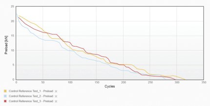
Figure 5. Three control reference tests conducted on an unsecured bolted joint without locking element.
5.2 Second step: comparing different anti-loosening solutions
The next stage is to conduct the verification test. The exact same test conditions are set, including the same effective displacement. Then, the locking product is introduced, and the secured bolted joint is tested to determine whether and at what point the secured bolted joint starts to loosen. Several verification tests must be made in order to ensure the test reproducibility (Fig. 6).
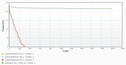
Figure 6. Verification test of the fastener secured with the locking product, under the same test conditions as the control reference tests from Fig. 5.
5.3 Analysing and reporting according to DIN 25201-4 B and ISO 16130
The results of the clamping force against the number of load cycles must be plotted in a graph. The securing performance is then assessed according to the percentage of preload remaining after a set number of load cycles. On the graph, the curve must show that it is unlikely that the fastener would have failed if the test continued.
In the test report, the type of locking mechanism and its fitting position must be described, as well as the test frequency, clamp length to diameter ratio, clamping, effective transverse displacement and lubrication used.
The final part of the report should detail the conditions under which the fastener’s securing element can be used and, if the test determined it, the level of pre-stressing force at which the fastener can be expected to fail. Details such as lubrication, surface coatings and the range of diameters are also required. Refer to the official standards for the complete list of information that should be indicated.
Conclusion
Analysing the self-loosening behaviour of fasteners is a critical step to ensure the safety of assembled parts. Even though computer modelling and simulation are progressing, the experimental approach by applying cyclic transverse force on fasteners under preload is still the most valuable method to evaluate their anti-loosening performance. Tracking the reduction of the clamping force under vibration can be complemented with torque-tension relationship analysis and transverse force and displacement measurements to obtain a broader understanding of the fastener behaviour and calculate actual friction values, all of which can be used to select the ideal fastener for each application.
Standardised protocols according to DIN 25201-4 B or ISO 16130 can be applied to run these tests. Alternatively, bespoke “tested-by-me” protocols can be designed to better reflect the real service conditions of the bolted joint.
References
1. German national standard, DIN 25201-4:2010 Anhang B, „Prüfvorschrift zum Nachweis der Losdrehsicherheit von gesicherten Schraubenverbindungen“ (2010)
2. P. R. Bonenberger, “Fastening: The Truth About TORQUE and TENSION”, Assembly Magazine, (Sept. 2001), http://www.assemblymag.com/articles/83789-fastening-the-truth-about-torque-and-tension
3. R. Friede, J. Lange, “Self-loosening of prestressed bolts”, in: Nordic Steel Construction Conference, Malmö, Sweden (Sept. 2009), http://www.nordicsteel2009.se/pdf/106.pdf
4. G. H. Junker, “New Criteria for Self Loosening of Fasteners under Vibration”, SAE International Automotive Engineering Congress, Paper No. 690055, pp. 314-335 (1969)
5. International standard ISO 16130:2015, “Aerospace series – Dynamic testing of the locking behaviour of bolted connections under transverse loading conditions (vibration test)”, International standard organisation (2015), https://www.iso.org/standard/55728.html
6. S. Saha, S. Srimani, S. Hajra, A. Bhattacharya, S. Das, “On the anti-loosening property of different fasteners”, Proceedings of the 13th NaCoMM Conference on Machines and Mechanisms (NaCoMM), IISc Bangalore, India, pp. 229–232, (2007), https://www.researchgate.net/publication/267971666_On_the_Anti- Loosening_Property_of_Different_Fasteners
7. A. Bhattacharya, A. Sen, S. Das, “An investigation on the anti-loosening characteristics of threaded fasteners under vibratory conditions”, in Mechanism and Machine Theory, 45(8): 1215-1225, (2010), https://www.researchgate.net/publication/245126630_An_investigation_on_the_anti- loosening_characteristics_of_threaded_fasteners_under_vibratory_conditions
8. S. Samanta, S. Das, R. Roy, K. Bhukta, A. Pal, S. Das, “Comparison of Anti-Loosening Characteristics of Various M14 Threaded Fasteners”, Indian Science Cruiser, vol. 26, No. 6, pp. 22-27 (2012), https://www.researchgate.net/publication/265252303_Comparison_of_Anti- Loosening_Characteristics_of_Various_M14_Threaded_Fasteners
9. U. Ince, B. Tanrıkulu, E. Kılınçdemir, S. Yurtdaş, C. Kılıçaslan, “Experimental investigation on self-loosening ofpreloaded stainless steel fasteners”, in Third International Iron & Steel Symposium, Karabük, Turkey (Apr. 2015), https://www.researchgate.net/publication/313932262_Experimental_investigation_on_self- loosening_of_preloaded_stainless_steel_fasteners
Learn more about the Dynamic Vibration Testing of Fasteners.
The original publication is available at www.mattech-journal.org